| Profiles |
|
| Customer defined profiles |
Up to 15 user programmable profiles Profiles are preset configurations where the customer can set the gas, range, dynamics, totalizers, engineering units and reference conditions for up to 15 different applications |
| Performance Data |
|
| Accuracy |
A1 Core: ± 0.5% of user full scale ± 1% of measured value.
B1 Prime: ± 0.3% of user full scale ± 0.7% of measured value.
B2 Prime high accuracy: ± 0.3% of user full scale ± 0.5% of measured value.
For hydrogen applications:
B3 Prime H2: ± 0.3% of user full scale ± 0.7% of measured value.
B4 Prime H2 high accuracy: ± 0.3% of user full scale ± 0.5% of measured value.
User full scale = ~70…100% standard range. |
| Media |
All gases and gas mixtures that are compatible with the selected materials and for which data is
available in the NIST refprop database.
Contact the factory for more information. |
| Dynamic range |
Fixed dynamics: 1 : 100 for most gases* VADy® dynamics: up to 1 : 1000 (available for meter only) VADy® or a fixed dynamic range can be selected during order process.
This setting can be changed at any time using the Vögtlin Connect app.
*The dynamic range is gas and pressure dependent, higher pressures means lower dynamic range. |
| Response time |
Meter: 120 msec / Controller: 2000 msec (according to SEMI standard SEMI E17-1011)*
Update time mass flow value: 10 msec / Sensor sample rate: 1 msec
*With optimized filter settings. All filter modes and values can be set through the Vögtlin Connect app or the digital communication interface. |
| Repeatability |
± 0.2% of factory full scale (according to SEMI standard E56-0309) |
| Longterm stability |
Typical < 0.2% of measured value / year after tare |
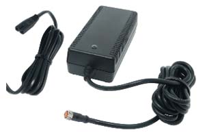
| Power supply |
Meter: 15-36 Vdc, (200 mA@24Vdc, regulated) / Controller: 24 Vdc ±10%, (2000 mA@24Vdc, regulated)
Power in through M8-4P connection or optionally through D-sub connection
(ripple should not exceed 100 mV peak-to-peak) We recommend that the body of this unit is properly connected to ground |
| Operation pressure |
1 to 14 bar a |
| Temperature (environment/gas) |
-20 to +60 °C (-4 to 140 °F) |
| Humidity gas |
0-95% Rh (non-condensing) |
| Pressure sensitivity |
Prime and Prime H2 sensor: <0.05% factory full scale per bar (typical air).
Core sensor: <0.08% of factory full scale + 0.1% of measured value per bar (typical air). |
| Temperature sensitivity |
<0.02% FFS* per 1 °C of inlet gas temperature @ 7 bar a pressure
*Factory Full Scale (maximum flow range of the device) |
| Accuracy temperature |
Typically ± 0.5 °C (not certified) |
| Accuracy absolute pressure |
<0.5% MV (not certified) |
| Warm-up time |
<2 sec for full accuracy |
| Materials |
|
| Wetted parts |
Elastomers: FKM, EPDM, FFKM (valve seat). Full FFKM version upon request.
Body: Stainless-steel 316L (1.4404).
Valve (controller): 316 (1.4401), 416 (1.4005), 430F (1.4104).
Inlet filter: Stainless-steel 316 (1.4401), fastening stainless-steel (1.4122) or equivalent.
A1 core sensor: Stainless-steel 316Ti (1.4571), silicon, gold, glass, silicone encapsulation, PBT. 30GF, ceramics.
B1 + B2 Prime sensor: Stainless-steel 316L (1.4404).
B3 + B4 Prime H2 sensor: Stainless-steel 316L (1.4404) with gold coating. |
| Electronic housing |
Powder coated stainless steel |
| Integrated inlet filter |
50 micron SS316 (1.4401) filter. Fastener filter material stainless-steel (1.4122) or equivalent. |
| Wetted part surface roughness |
1.6 Ra µm or better (contact factory for lower Ra values) |
| Integration & Installation |
|
|
|
| Output signals analog |
Linear 4–20 mA or customer defined (max 20 mA), user selectable
Linear 0–5 Vdc or 0-10 Vdc or customer defined (max 10 Vdc), user selectable
mA output: 740 ohms maximum load resistance
Volt output: 1000 ohms minimum load resistance
All analog outputs are galvanically separated and protected. If used with analog signals add + as before 0.2% of FFS to the uncertainty |
| Setpoint signals analog |
Linear 4–20 mA or customer defined, (max 20 mA) user selectable
Linear 0–5 Vdc or 0-10 Vdc or customer defined, (max 10 Vdc) user selectable |
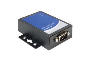
| Output signals digital |
RS-485 (Modbus RTU 2-wire)
The Modbus address can be set with 2 rotary switches on the outside of the housing.
All Modbus settings can be set through the Vögtlin Connect app. |
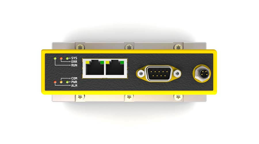
| Optional Profinet or EtherCAT |
Dual port RJ45 with integrated switch (easy to daisy chain)
RJ45 LEDs indicating link and activity on the network / Ethernet speed: maximum 100 Mbit
ProfiNet: PROFINET IO specification v2.33 / PROFINET IO devices conformance class B (RT) / Endianness: conform Siemens S7 (big)
EtherCAT: IEC standard IEC61158 / Endianness: little
EtherNet/IP™ coming soon. |
| Configuration interface |
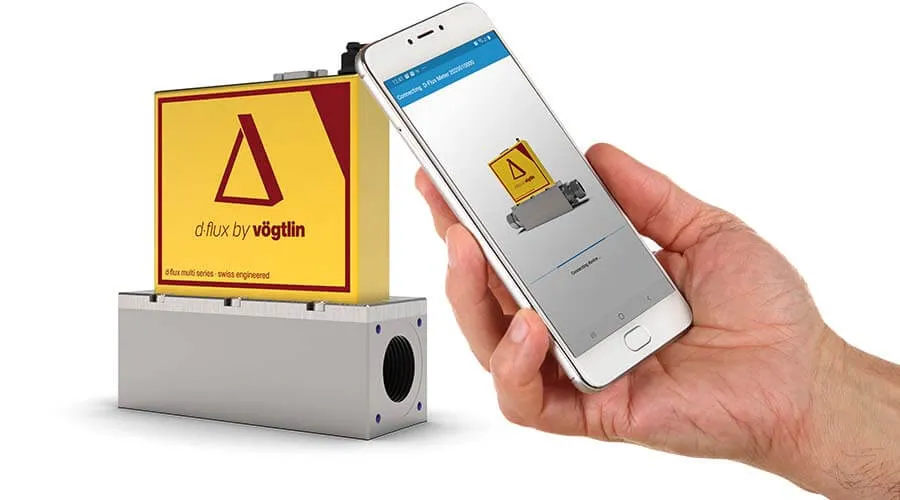
Wireless Vögtlin Connect app available from Google Play store |
| Output I/O MOSFET |
On/off for external shut-off valve or alarm available through M8-4P connector
Contact type: MOSFET (open drain/collector)
Maximum voltage: 36 Vdc, Max current 500 mA (Polyfuse protected) |
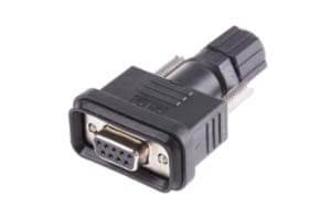
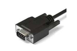
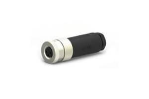
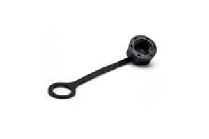
| Electrical connection |
9-pin D-sub male (power and signals) and M8-4P connector (Power + I/O MOSFET output)
Optional 2 x RJ45 (EtherCAT / Profinet) |
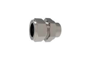
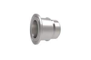
| Process connection |
1″ BSPP female (1″G)
Optional ½” BSPP, 1″ Compression or Tri-clamp 50.5mm flange size (ISO) (see accessories tab) |
| Inlet section |
None required if our standard inlet filter / conditioner is installed
Without filter / conditioner a 10 D straight inlet is recommended
The inlet filter can be deselected at time of order |
| Pressure drop |
Meter: Standard 400 mbar at factory full scale air venting to atmosphere (with filter / conditioner)
Optional: 325 mbar at factory full scale air venting to atmosphere (without filter / conditioner)
Pressure drop is dependent on operating pressure (higher pressure = lower pressure drop)
For more information please refer to your sales partner
Controller: Min. pressure difference required for 1400 ln/min (air) < 2 bar
Contact your sales partner for other pressure drop requirements |
| Mounting orientation |
All orientations are possible |
| Weight |
Meter: 3.7 kg, Controller: 8.7 kg (excluding ethernet and fittings) |
| Safety |
|
| Test pressure after production |
28 bar a |
| Maximum overpressure sensor |
Core Sensor: 28 bar a, Prime and Prime H2 Sensor: 90 bar a |
| Burst pressure |
Meter: 100 bar a, Controller: 70 bar a |
| Leak rate |
< 1 x 10⁻⁶ mbar l/s He |
| Ingress protection class |
IP54, if IP54-D-sub is used (see accessories tab)
For optional EtherCAT/Profinet: IP40
For additional safety information please consult the d·flux safety information sheet available on our website |
| Certifications |
|
| EMC |
IEC/EN 61326-1, IEC/EN 61000-6-2/4 |
| ATEX certification |
None |
| Material certificates |
To be released in 2023 (available for meter only) |
| FDA compliance |
To be released in 2023 (available for meter only) |
| PED |
Fully compliant. Since the unit has 1″ process connection, complies with the SEP, as defined in article 4, paragraph 3 of the Pressure Equipment Directive (PED) (2014/68/EU) |
| RoHS / REACH |
All components comply with Directive 2002/95/EC (RoHS) and the REACH guidelines |
| Warranty |
3 years, excluding cases of corrosion
|